B16a swap in progress, couple questions

My 2nd gen b16a is in, I’ve come across a couple questions!

First what are these and what do they do (the two black things, with the 4 lines). I have no clue where to connect these (vaccum?) lines

2nd, I have two extra electrical plugs on my OBD-0 harness that I have no idea where they plug into on the b16a. The one pictured below is near the distributor and such, and the other one was originally connected to the sensor around the oil filter, that has two prongs and has a green top, this connector also has a large boot around it.

Thanks for the insight, much appreciated

http://hondapartsunlimited.com/prddisplay.php?inputstate=5&make=Acura&model=INTEGRA&year=1993&version=3DR+GS&transmission=KA5MT&section=LIST+ALL&ListAll=All&vinsrch=no&imageID=203460&illustrationID=950&illustration=CONTROL%20DEVICE

MAP sensor - as I recall - I needed to install a T fitting at the manifold for the vacuum line.

You will need to either make or purchase a conversion harness to marry the B16A to your chasis. Lots of sensors etc (Vtec, knock sensor, oil temp, etc) either do not match up, are not used, or need to be added. Either way you will need to extend 2 wires and connector pins from the new ECU through the firewall for Vtec operation, since the chasis wiring does not have these leads. Also think about cable clutch conversion and motor mounts.

Lots of write ups on this conversion exist - do a search
Here area few:
http://www.autosoftsys.com/supra/ecuext/
http://hondaswap.com/swap-articles/engine-removal-guide-29124/
http://www.honda-tech.com/showthread.php?t=833163
http://ef-honda.com/ben/EFwiring.php
http://www.g2ic.com/tegtips/engine/Engine_Swap_Guide.doc

I Have already added vtec and o2 wires. and have extended the coolent temp switch. I guess what I’m asking is are the two plugs I don’t have a home for needed for the b16a.

Anyone have a vacuum diagram? or can anyone tell me where the top line from the two purge valve’s go’s and the bottom lines! THANKS

I removed mine, they look like purge soleniods to me.

Yes they are, I think I got it wired up correctly now. Found a diagram somewhere. I wired one of the purge’s to the charcoal canister and the other line to the IM. the other one I wired to the vaccum line coming off the fuel return (at the top) and the other to the IM. I need to use a T. Is this right?

Also anyone know what that plug is for?

anyone? Bump

Sounds like you may have gotten a bit confused w/ the wires.

The sensor on the back of your block w/ the two wires and “boot” should be your ECT switch wires. You’ll need to move those to attach to the ECT switch which is now on your thermostat.

As for that connect pictured above (cream colored) how many wires are coming out of it? And what color are they? There are a couple different plugs which use that same basic style of connector. TPS and MAP sensors come to mind. Are both of those plugged in on your car? You may also need to consider that your MAP sensor may have moved if your new engine has the MAP sensor integrated onto the throttle body opposed to on the firewall how it is shown in your photo.

The MAP sensor plug is still plugged into the MAP sensor in the pic above next to the Purge Solenoids. So that rules that one out for the MAP. I would say most likely the TPS (throttle position sensor) located on the throttle body since its over close to the distributor. If it’s not that, it would most likely be the IACV located on the back of the intake manifold. As far as the 2 wire connector on the back of the block with a rubber boot, that would be an oil temperature sensor. It’s used on older obd0 engines to turn the cooling fan(s) on when oil temperatures reach a certain threshold. I forget what temp it is. I don’t think you’ll have that sensor on a b16. I deleted mine on my B20 vtec.

To be more specific, the wires are Green, Red/Blue and Yellow and the location of the plug is on the harness a couple inches before the injector wiring.

As for the plug with the boot, It pluged into this on the b18a. I already have a plug plugged into my thermostat. so is this needed or have I wired things up wrong?

That was perfect info. Confirmed with Helms, the connector with Yel/Wht, Red/Blu, Grn/Wht is TPS. Will be on the firewall side of your throttle body. The other is the Oil Temp Sensor, and can be deleted.

Thanks a ton :rockon:

You are right only if you assume he’s doing everything correctly. Depending on the exact engine he has the MAP sensor could be ON the throttle body and it has yet to be determined what, if anything, he had done regarding that factor. You’ll notice that I mentioned this briefly in my post.

Dew, that piece you just took a photo of is your ECT switch. The wires that went to that need to connect to the ECT switch which is now on your thermostat. The connectors used are different, so you’ll need to cut the connector off of the engine harness which came with your engine and solder that connector onto your original engine harness.

Not sure what ninezero is talking about in regard to an oil temp sensor, because there isn’t one located on the back of the block.

I would suggest doing a search for “ect” you’ll get a lot of good info about the ECT sensor, switch, and sending unit as well as a lot of the other pieces which commonly get confused with them. Here’s one OLD post which talks some about this: http://www.g2ic.com/forums/showthread.php?t=41506&highlight=ect

Let me clarify it for you then. Maybe I was mistaken in its proper name. It is actually an Oil Temp Switch, not sensor. You clearly talk about it being on the back of the block in the post you linked the OP to. It’s also in the Helms, and shows to have WHT/GRN and BLK whire going to it.

I believe Colin is right because the sensor smells like coolent, not oil

Sorry for being such a stickler when it comes to the differences between sensors, switches and sending units, but I feel it is mandatory. I doubt you understand how often over the years I have had to constantly correct people on this stuff to help someone out. There is completely rampant confusion and misinformation regarding the ECT sending unit, switch, and sensor, combine that with the fact that the ECT switch is also commonly referred to as the “Thermo water switch” or the “fan switch” and you’re in a heap of trouble semantically… Then combine that with the fact that there are the Oil switches and sending units and the ECT switch differences between years, and that a lot of these pieces look similar… and you’re in even more trouble.

The only way to keep everyone on the same page with this stuff is if everyone uses the same terminology and really thinks before they post. And I hold myself to that same standard. While typing the above post I did not do it simply off the top of my head. I made a couple quick searches to confirm my sometimes failing memory so that I could be confident that the info I was posting was correct. I wish everyone else on here did the same.

Either way, the switch in the photo has nothing to do with oil. That is the ECT Switch (obd0 style). The Oil temp switch on the back of the block looks completely different.

Okay so how do I wire this up lol…i’ve extended the wires, and the plug from the obd1 harness has green/white and red/white wires. Where do my black and yellow/green wires connect :S …

Oh, and so I don’t look like a total idiot, the reason why I couldn’t find the 3 prong TPS plug was the male end was broken off, so I just used the one of my LS

It’s a switch, so it doesn’t matter which side goes to which. Glad to hear you got everything figured out.

[QUOTE=dew1989;2057770]Okay so how do I wire this up lol…i’ve extended the wires, and the plug from the obd1 harness has green/white and red/white wires. Where do my black and yellow/green wires connect :S …

Oh, and so I don’t look like a total idiot, the reason why I couldn’t find the 3 prong TPS plug was the male end was broken off, so I just used the one of my LS[/QUOTE]
Re-read this entire post and all of my responses, it seems as if you’ve extended the wrong wires. Also, do you not have a helms manual? If you do, why aren’t you using it? If you don’t, why haven’t you bought one?

The blk and yel/grn wires are for the ECT switch. These need to be connected to the ECT switch on your thermostat housing. In order to do this you not only need to extend the wires, but solder on a new type of connector (just use the connector off of your obd1 engine harness).

For reference, here is a pic of the thermostat housing from my b17a showing the ECT switch with connector attached. As you can see, wire colors are blk and yel/grn. Those colors are also listed in the Helms.

The engine oil temp switch should have a blk wire and a wht/grn wire. Your OBD0 engine harness should have this connector for this, but there’s a chance you don’t have an engine oil temp switch on your b16a. Different models of cars with different options needed this switch for different things. for instance, USA models w/o AC and CDM models w/ AC did not have this switch. However USA models w/ AC did have the switch.

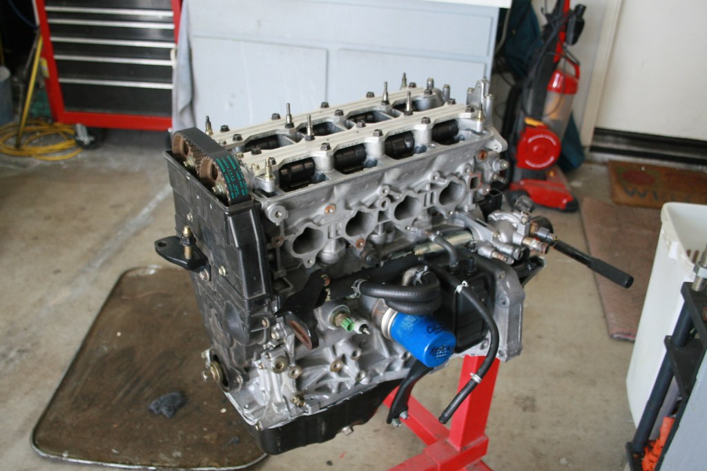
In THIS photo you can see the Engine Oil Temp switch (it’s to the left of the oil filter and green in color). You’ll notice that it looks basically exactly the same as the OBD1 ECT swtich.

Don’t worry, I didn’t forget about the grn/wht and red/wht wires you mentioned… Sounds like you extended the wires which were for the ECT Sensor. The ECT sensor uses those wire colors (per my experience and confirmed w/ Helms manual).

The ECT sensor is located on the distributor side of the head on both vtec and non-vtec heads. They are in slightly different locations due to the addition of the vtec solenoid, but they’re only a few inches different. The connector used for the ECT Sensor is the same as the OBD1 style ECT Switch.

For reference, here is a photo showing the location of the ECT Sensor on my b17a head. You can see the gray connector directly under the vtec solenoid. IIRC the sensor itself is a white color. Sorry I don’t seem to have a better pic of the sensor unplugged.

Well whatever I did isn’t giving me any code’s or anything, so once i get it on the road we’ll see if all is good the way it is… And i do have a helms, but obviously it doesn’t mention anything for the b16a.

On a side note, I’m having some MAJOR problems putting my axle’s back on. I’ve got 2 “square” rollers and 4 circular rollers. My manual is confusing the hell out of me. Do the two square’s go on the passenger side or do I put one on the pass and one on the driver. Have any tips? I am desperate…

Thanks for all your help!